#labview based projects
Explore tagged Tumblr posts
Visit Tumblr Blog
Explore Tumblr blogs with no restrictions, modern design and the best experience.
Last Seen Tumblr Blogs


Fun Fact
Tumblr has a low social media market share in South America.
Text
Best EEE College in Villupuram for Placements, Faculty & Campus Life
Choosing the right engineering college can make or break your career—especially if you’re planning to specialize in Electrical and Electronics Engineering (EEE). In a region like Villupuram, where options are many but quality varies, students often ask the question: “Which is the best EEE college in Villupuram?”
The answer, based on academic excellence, top-tier placements, expert faculty, and holistic campus life, is undoubtedly Manakula Vinayagar Institute of Technology (MVIT).
In this blog, we dive deep into what makes MVIT the best EEE college in Villupuram—focusing specifically on its placement success, faculty strength, and enriching campus life.
🌟 Why MVIT Stands Out in EEE Education
MVIT’s Department of Electrical and Electronics Engineering is recognized for blending academic theory with practical application. With a modern curriculum, cutting-edge labs, and an unwavering focus on student outcomes, MVIT offers an EEE program that’s not just future-proof—but future-forward.
➡️ Department link: https://mvit.edu.in/departments/eee/
💼 Placements: Your Career Starts Here
One of the biggest reasons why MVIT is considered the best EEE college in Villupuram is its outstanding placement record. The college has built a strong reputation among recruiters thanks to its skilled graduates and industry-oriented training.
✅ Top Companies That Hire MVIT EEE Graduates:
Tata Power
Siemens
Ashok Leyland
ABB
Infosys
Zoho
Wipro
Cognizant
TVS Group
L&T Technology Services
With support from an active placement cell, students receive specialized training in:
Aptitude and reasoning
Technical interviews
Soft skills and group discussions
Resume building and mock interviews
🎯 Real Success Stories
Many EEE students from MVIT have bagged dream roles in core companies with competitive packages, while others have pursued higher education in IITs, NITs, and top international universities.
The consistent placement performance of MVIT proves its capability to prepare students not only for jobs but for long-term careers in electrical engineering, automation, and embedded systems.
👨🏫 Faculty: Learn from the Best
What’s an engineering college without exceptional faculty?
MVIT’s EEE department is home to highly qualified, passionate, and experienced faculty members, many of whom hold PhDs and have published work in international journals. Their pedagogy goes beyond textbooks, as they:
Engage in real-world R&D projects
Encourage student innovation and research
Provide mentorship for competitive exams like GATE, GRE, and UPSC ESE
🧑🏫 Faculty Strength Highlights:
Regular guest lectures by industry experts
One-on-one mentorship
Hands-on teaching methodology
Guidance on academic publishing, patent filing, and entrepreneurship
Faculty at MVIT are not just teachers—they’re career mentors, research guides, and role models for aspiring engineers.
🧪 Infrastructure & Labs: Where Theory Meets Practice
MVIT’s EEE department has some of the best infrastructure in Villupuram. Students have access to fully-equipped, industry-grade laboratories including:
Power Electronics Lab
Control Systems Lab
Electrical Machines Lab
Embedded Systems Lab
Renewable Energy Lab
Students get hands-on experience with advanced tools like MATLAB, Proteus, LabVIEW, and PLC/SCADA kits, ensuring they’re industry-ready before they graduate.
🧭 Campus Life: A Perfect Balance of Learning & Living
Engineering isn’t only about books and exams—it’s also about growing as a person. MVIT offers a vibrant campus life that helps students develop leadership, creativity, communication, and confidence.
🏫 Clubs and Student Chapters:
IEEE Student Chapter (actively conducts workshops and paper presentations)
Renewable Energy Club
Robotics and IoT Club
Coding and Hackathon Groups
Cultural and Literary Societies
🎉 Campus Events:
MVIT hosts several national-level technical symposiums, cultural festivals, and inter-department sports meets, giving students opportunities to showcase their skills and build lifelong friendships.
The campus also includes:
A green and Wi-Fi enabled environment
Well-stocked library
Digital classrooms
Cafeteria, gym, and sports grounds
Separate hostels for boys and girls
With holistic development at its core, MVIT creates a 360-degree experience that blends academics, skill-building, and leisure.
📚 Curriculum & Certifications: Learn What Matters
MVIT’s EEE curriculum is aligned with Anna University guidelines, but with a modern twist. It includes value-added courses and certifications that help students stay ahead of the curve:
IoT & Embedded Systems
PLC & SCADA
Python Programming
Solar PV System Design
Machine Learning in Electrical Engineering
These certifications are offered through partnerships with industry leaders and online platforms, helping students earn job-ready skills even before their final year.
🌐 Global & Industrial Exposure
MVIT believes in preparing students for global careers. That’s why the EEE department organizes:
Industrial visits to TANGEDCO, BSNL, and private power companies
Internships and mini-projects with reputed industries
MoUs with industries for training, internships, and placements
Research collaborations with government and private institutions
This continuous industry-academia interaction ensures MVIT students remain relevant and competitive in the job market.
🎓 Alumni Network & Career Growth
MVIT’s EEE alumni have made their mark across sectors—be it core electrical firms, IT giants, public sector undertakings, or higher education institutions. The strong alumni network also helps current students with:
Career guidance
Industry referrals
Guest lectures
Internship opportunities
Some alumni have also gone on to start their own companies, showing the entrepreneurial spirit fostered at MVIT.
📌 Conclusion: Your Journey Starts Here
When you’re searching for the best EEE college in Villupuram, you need a college that offers not just a degree—but a launchpad for your dreams.
Manakula Vinayagar Institute of Technology (MVIT) is that place.
With top-notch placements, world-class faculty, immersive campus life, and hands-on learning opportunities, MVIT's EEE department checks all the boxes for a fulfilling and successful engineering journey.
👉 Start your future here: https://mvit.edu.in/departments/eee/
0 notes
Text
Open source 24-channel USB high-voltage driver
When it comes to automation and control systems, there's often a need for multiple digitally controlled output terminals with high-voltage handling capabilities. Many existing modules are bulky, expensive, or require numerous additional components to function. To address this gap, I've developed a fully open-source, USB-controlled 24-channel high-voltage driver. This device provides precise, flexible control in a compact and user-friendly package. The project is open hardware, released under the CERN-OHL-W license, ensuring transparency from hardware schematics to firmware code. The driver module communicates via USB using a simple virtual COM port, eliminating the need for special drivers and complex setups.

At the core of the system are three TPIC6B595 shift registers, each supplying eight open-drain outputs that can handle up to 50V and sink currents of up to 150mA per channel. These registers are daisy-chained to achieve a total of 24 outputs. The outputs are designed for low-side switching and include integrated clamping diodes, making them suitable for driving inductive loads such as relays and solenoids. Data is clocked into the registers through serial input from a microcontroller, allowing for fast and reliable state updates across all channels with just a few lines of code.
The logic and communication for this module are managed by the STC15W204S microcontroller, a cost-effective yet powerful 8051-based MCU with enhanced UART performance and an integrated oscillator. This chip is paired with a CH340N USB-to-UART bridge, which presents the device as a standard virtual COM port to the host PC. Upon connection, the microcontroller listens for a set of AT-style commands sent over the serial connection. These commands are straightforward and user-friendly, for example, "ON=65280" activates the middle 8 outputs, "CLR" turns off all channels, and "VER" retrieves the firmware version. Additionally, there is a command to save the current output state to the built-in EEPROM, enabling the system to restore its output to a known state after power cycles. This interface design is perfect for scripting, automation, or integration with software tools such as Python, LabVIEW, or custom control GUIs.
The PCB is designed using KiCad and features a 2-layer layout measuring 75.25mm × 33.75mm. It includes 2.54mm pitch headers for output connections and is equipped with a USB Type-C connector. Power can be supplied through either USB or an external regulated 5V source, which can be selected via onboard jumper settings. The layout ensures clean signal routing and minimizes crosstalk or interference, even when switching high-voltage loads. Careful decoupling and protection components provide robustness for real-world applications.

The PCB for this module was fabricated by PCBWay, who generously sponsored this project. PCBWay offers high-quality PCB manufacturing and assembling services. Also, they offer CNC and 3D printing services. The PCB of this module is available to order from PCBWay. Check out the PCBWay website for its manufacturing capabilities and pricing.
The firmware for the STC15W204S is written in C using SDCC. It is easy to expand the command set, introduce new communication modes, or add timed control logic as needed. The current implementation allows full 24-bit output control using a base 10 numerical mask, making it both scriptable and human-readable. Thanks to the preloaded bootloader of the STC15W204S, firmware updates can be performed through the same serial interface. Details about this process are covered in the project documentation. Like the hardware, the firmware is released under the MIT License and is available in the project repository.
The system has been tested with a variety of 12V and 24V inductive and resistive loads, including relay banks, solenoids, and LED arrays. Since the outputs are open-drain, external voltages up to 50V can be safely switched on each channel making it ideal for a range of industrial, laboratory, or artistic applications. Output timing is reliable, with clean edge transitions observed during scope testing, and no signal integrity issues even during full 24-channel toggling. It is recommended to use individual heatsinks for the driver ICs when driving high-current inductive loads with this module. While the printed circuit board has heat transfer traces, the addition of individual heatsinks can increase the durability of the module.

Potential use cases for this module include automated test benches, home automation systems, signal routing for instrumentation, nixie tube multiplexing, and other high-voltage control tasks. The command-based protocol makes it easy to script operations or integrate this module into a larger system.
For those who wish to explore the schematics, command protocol, design rationale, and usage examples in greater depth, I have published comprehensive documentation and resources in the project wiki. This includes detailed assembly instructions, firmware flashing guidance, and tips on customizing the firmware for enhanced functionality.
All source files - including schematics, PCB layout, firmware code, and the bill of materials - are freely available at https://github.com/dilshan/24ch-usb-high-voltage-driver.
0 notes
Text
Off-Site Engineering Services: A Smart Approach to Scalable Innovation

In an increasingly global and fast-paced engineering environment, companies are under constant pressure to innovate quickly, reduce time-to-market, and manage operational costs. One solution that has gained significant traction in recent years is Off-Site Engineering Services. This model allows organizations to outsource specialized engineering tasks to remote teams while maintaining quality, compliance, and project timelines.
Off-site engineering has transformed how businesses approach product development, R&D, and system integration. It provides flexibility, scalability, and access to global talent without the overhead of in-house hiring or infrastructure expansion.
What Are Off-Site Engineering Services?
Off-site engineering services involve delegating design, development, analysis, and support tasks to a dedicated team located outside the client’s physical premises. This team may operate from a different city, state, or country, often functioning as an extension of the client’s internal engineering department.
Services typically provided off-site include:
Product design and development
CAD modeling and FEA analysis
Embedded system design
Control system development
Simulation and testing
Software and firmware development
Documentation and compliance
These services are supported via cloud-based collaboration tools, secure data access protocols, and regular project reviews, ensuring transparency and control.
Key Benefits of Off-Site Engineering Services
✅ Cost Efficiency
Off-site engineering significantly reduces costs associated with full-time staff, training, office space, and tools. Companies can scale engineering resources up or down based on project demand without long-term commitments.
✅ Access to Global Talent
With off-site services, companies can tap into a broad pool of skilled engineers and domain experts across the globe. This access accelerates innovation and ensures technical challenges are handled by specialists.
✅ Faster Time-to-Market
By delegating parallel tasks to off-site teams, in-house engineers can focus on core innovations. This concurrent development approach shortens project timelines and speeds up product launches.
✅ Focus on Core Competencies
Organizations can offload routine or time-consuming engineering tasks and concentrate on strategic initiatives like product differentiation, customer engagement, and business growth.
✅ Business Continuity
Off-site teams can provide backup during employee transitions, holidays, or workload surges. They also ensure project continuity in the face of unexpected disruptions like local resource shortages.
Applications Across Industries
Off-site engineering services are applicable across a wide range of industries, each benefiting from the flexibility and scalability this model offers:
Automotive: Control systems, ECU software, infotainment systems, electric vehicle (EV) architecture, and simulation.
Aerospace: Avionics systems, structural analysis, CAD modeling, and compliance documentation.
Industrial Automation: PLC programming, HMI development, motion control, and system integration.
Medical Devices: Regulatory documentation, embedded software, prototyping, and product design.
Renewable Energy: Solar and wind system modeling, battery management systems, and grid integration support.
Consumer Electronics: IoT device design, firmware development, and wireless communication solutions.
Key Services Offered in Off-Site Engineering
CAD and Product Design
3D modeling, rendering, and drafting using tools like SolidWorks, CATIA, and AutoCAD.
Design for manufacturability (DFM), design reviews, and rapid prototyping support.
Control System Development
PID controller tuning, mechatronics integration, and custom control logic.
Simulation tools like MATLAB/Simulink and LabVIEW for testing and validation.
Embedded Systems and Firmware
Microcontroller programming, real-time operating systems (RTOS), and IoT device firmware.
Protocol integration (CAN, LIN, Modbus, Ethernet).
Testing and Validation
Software-in-the-Loop (SIL), Hardware-in-the-Loop (HIL), and model-in-the-loop (MIL) testing.
Automated test case development and execution.
Simulation and Analysis
Finite Element Analysis (FEA), Computational Fluid Dynamics (CFD), and system-level modeling.
Structural, thermal, and dynamic simulations for design optimization.
Documentation and Compliance
Support for ISO, AS9100, FDA, and other industry-specific compliance documentation.
Technical manuals, BOM creation, and version control.
Off-Site vs. On-Site Engineering: A Comparison
Feature
Off-Site Engineering
On-Site Engineering
Cost Efficiency
High
Moderate to Low
Talent Access
Global
Local/Regional
Scalability
Flexible
Fixed resources
Control and Supervision
Remote, process-driven
Direct, face-to-face
Infrastructure Cost
Minimal for client
High (workspace, equipment)
Collaboration Tools
Digital (Zoom, Slack, etc.)
Physical meetings, systems
While on-site engineering offers direct interaction, off-site engineering provides a cost-effective and scalable model that aligns with modern development cycles and distributed teams.
Best Practices for Successful Off-Site Collaboration
Clear Communication Protocols: Establish regular stand-ups, updates, and feedback loops.
Defined Scope and Deliverables: A clear SOW (Statement of Work) ensures alignment.
Secure Data Handling: Use VPNs, secure servers, and IP protection agreements.
Project Management Tools: Platforms like Jira, Asana, or Trello help track tasks and milestones.
Regular Reviews and QA: Frequent quality checks ensure project progress and adherence to standards.
Why Choose Off-Site Engineering Today?
With remote work now the norm and global collaboration tools more advanced than ever, off-site engineering offers a practical solution for companies aiming to innovate without the traditional limitations of location and infrastructure. Whether you're a startup scaling quickly or an enterprise optimizing operations, off-site engineering can deliver high-quality results with speed and efficiency.
Conclusion
Off-site engineering services at Servotech Inc are revolutionizing how engineering work is done across industries. By providing access to expert talent, reducing costs, and accelerating time-to-market, this model allows businesses to stay competitive in a demanding technological landscape. When executed with strategic planning and the right partners, off-site engineering is not just an outsourcing strategy—it’s a pathway to smarter, more agile innovation.
0 notes
Text
Exploring Electronics and Communication Engineering in Hyderabad: Education, Careers, and Opportunities
Electronics and Communication Engineering (ECE) has emerged as one of the most sought-after fields of study and employment in India, and Hyderabad stands out as a premier destination for aspiring engineers. Known for its thriving IT industry, top-notch educational institutions, and innovation-driven ecosystem, Hyderabad offers an ideal environment for ECE enthusiasts to grow and excel. To explore more about ECE programs, visit HITAM’s Electronics and Communication Engineering page.
Why Choose Hyderabad for Electronics and Communication Engineering?
Hyderabad, often referred to as India’s “Cyber City,” boasts a unique blend of traditional educational values and cutting-edge technology advancements. Here are a few reasons why it is a hub for ECE aspirants:
Top-Notch Educational Institutions: Hyderabad is home to prestigious engineering colleges such as the Indian Institute of Technology Hyderabad (IIT-H), Jawaharlal Nehru Technological University Hyderabad (JNTUH), and Osmania University. These institutions offer state-of-the-art infrastructure, experienced faculty, and industry-focused curricula that equip students with theoretical and practical knowledge. HITAM is another institution that provides excellent opportunities for ECE students.
Industry Ecosystem: The city houses numerous tech parks, multinational companies, and startups in electronics, telecommunications, and software industries. Companies like Qualcomm, Intel, and TCS have a significant presence here, providing ample internship and employment opportunities.
Emerging Startup Culture: Hyderabad’s startup culture is thriving, particularly in areas like IoT, robotics, and embedded systems. This opens doors for ECE graduates to work on innovative projects and develop entrepreneurial skills.
Affordable Living: Compared to other metro cities, Hyderabad offers a relatively low cost of living, making it an attractive destination for students and young professionals.
Scope of Electronics and Communication Engineering in Hyderabad
ECE encompasses a vast array of specializations, including telecommunications, embedded systems, VLSI design, signal processing, and networking. Here are some career pathways for ECE professionals in Hyderabad:
Telecommunications: With the growing demand for 5G technology, companies like Airtel and Reliance Jio frequently hire ECE professionals for roles in network design, testing, and optimization.
Embedded Systems: Hyderabad’s IT ecosystem supports embedded technology development, offering roles in hardware and firmware design.
Software Development: ECE graduates with programming skills can find opportunities in software development, especially in companies focusing on real-time applications.
Research and Development: Hyderabad’s research institutions and private labs frequently hire ECE graduates for cutting-edge research projects.
Tips for Aspiring ECE Students and Professionals
Focus on Practical Skills: Gain hands-on experience through internships, workshops, and project-based learning. Knowledge of tools like MATLAB, LabVIEW, and PCB design software can be a significant advantage.
Keep Updated with Trends: Stay informed about industry trends such as IoT, AI, and 5G to align your skills with market demands.
Build a Strong Network: Attend tech meetups, hackathons, and seminars in Hyderabad to connect with industry professionals and peers.
Leverage Online Resources: Platforms like Coursera, edX, and Udemy offer specialized courses that can enhance your expertise in niche ECE areas.
Conclusion
Electronics and Communication Engineering in Hyderabad offers a promising blend of quality education, robust industry exposure, and dynamic career opportunities. Whether you are an aspiring student or a professional looking to advance your career, Hyderabad provides the perfect ecosystem to thrive in the field of ECE. Start exploring your options today and become a part of this ever-evolving technological revolution. Learn more about ECE programs and opportunities at HITAM’s official page.
1 note
·
View note
Text
Maximizing NI-Based Test & Measurement Solutions for Unparalleled Precision
In today's dynamic technological landscape, where innovation is the driving force behind progress, NI-based test & measurement solutions stand out as indispensable tools for ensuring precision, reliability, and efficiency in various industries. As businesses strive to maintain a competitive edge and meet evolving market demands, leveraging advanced NI-based platforms becomes imperative for achieving unparalleled accuracy and performance in testing and measurement processes.
Understanding the Essence of NI-Based Test & Measurement
At the core of NI-based test & measurement lies National Instruments (NI), a renowned leader in providing cutting-edge hardware and software solutions tailored for engineering applications. With a legacy of excellence spanning decades, NI has revolutionized the field of instrumentation by offering versatile platforms that empower engineers and researchers to tackle complex challenges with ease.
The Versatility of NI Hardware and Software
One of the key strengths of NI-based test & measurement solutions lies in their unparalleled versatility. NI's extensive range of hardware, including data acquisition systems, modular instruments, and real-time controllers, caters to diverse testing requirements across industries such as automotive, aerospace, telecommunications, and beyond. Coupled with advanced software tools like LabVIEW, TestStand, and SystemLink, these platforms provide a comprehensive ecosystem for designing, deploying, and managing test systems with utmost efficiency.
Harnessing the Power of Modular Instrumentation
Modularity lies at the heart of NI-based test & measurement solutions, offering unparalleled flexibility and scalability to adapt to evolving project needs. With modular instruments, engineers can easily configure custom test setups by combining interchangeable modules tailored to specific measurement tasks. This modular approach not only streamlines development and deployment processes but also future-proofs test systems, allowing for seamless upgrades and expansions as project requirements evolve over time.
Advantages of NI-Based Test & Measurement Solutions
When it comes to NI-based test & measurement, the advantages are manifold, encompassing superior performance, reliability, and cost-effectiveness. Let's delve deeper into some of the key benefits that set these solutions apart:
Precision and Accuracy
At the forefront of NI-based test & measurement solutions is their ability to deliver unparalleled precision and accuracy in data acquisition and analysis. Whether it's capturing signals with high resolution, performing complex measurements with utmost fidelity, or achieving tight synchronization across multiple channels, NI's hardware and software platforms excel in ensuring reliable results that meet the most stringent standards.
Time-to-Market Efficiency
In today's fast-paced business environment, speed is of the essence, and NI-based test & measurement solutions offer a significant advantage in reducing time-to-market for new products and innovations. By leveraging modular instrumentation and intuitive software development environments, engineers can accelerate the prototyping, validation, and deployment phases of their projects, enabling quicker iterations and faster delivery of high-quality solutions to market.
Scalability and Flexibility
Another key advantage of NI-based test & measurement solutions is their inherent scalability and flexibility, allowing organizations to adapt to changing requirements and scale their test systems as needed. Whether it's adding new measurement channels, integrating additional sensors or interfaces, or expanding testing capabilities to cover a broader range of parameters, NI's modular platforms empower engineers to tailor solutions that grow in tandem with their business needs.
Total Cost of Ownership (TCO)
In addition to performance benefits, NI-based test & measurement solutions offer significant advantages in terms of total cost of ownership (TCO). By providing integrated hardware and software ecosystems, NI simplifies procurement, deployment, and maintenance processes, thereby reducing upfront costs and minimizing long-term operational expenses associated with managing disparate test systems from multiple vendors.
Applications Across Industries
The versatility and reliability of NI-based test & measurement solutions make them indispensable across a wide spectrum of industries, where precision and efficiency are paramount. From automotive manufacturing and aerospace engineering to telecommunications and renewable energy, these solutions find applications in diverse domains, enabling organizations to optimize performance, enhance quality, and drive innovation.
Automotive Industry
In the automotive sector, NI-based test & measurement solutions play a crucial role in ensuring the safety, reliability, and efficiency of vehicle components and systems. From testing electronic control units (ECUs) and powertrain components to validating advanced driver-assistance systems (ADAS) and autonomous vehicle technologies, NI's platforms enable automotive manufacturers to meet stringent quality standards and regulatory requirements while accelerating time-to-market for next-generation vehicles.
Aerospace and Defense
In the aerospace and defense sector, where reliability and precision are paramount, NI-based test & measurement solutions provide critical support for the development, testing, and maintenance of aircraft, spacecraft, and defense systems. From avionics testing and structural health monitoring to radar signal analysis and electronic warfare simulation, NI's platforms offer the performance and flexibility needed to address the complex challenges of modern aerospace and defense applications.
Telecommunications
In the telecommunications industry, where rapid advancements in wireless technologies drive connectivity and innovation, NI-based test & measurement solutions enable network operators, equipment manufacturers, and service providers to ensure the performance, reliability, and interoperability of communication systems. Whether it's testing 5G infrastructure, optimizing RF spectrum utilization, or verifying compliance with industry standards, NI's platforms empower stakeholders to deliver seamless connectivity experiences to consumers and businesses alike.
Renewable Energy
In the renewable energy sector, where sustainability and efficiency are driving forces behind the transition to clean energy sources, NI-based test & measurement solutions play a pivotal role in optimizing the performance and reliability of solar, wind, and energy storage systems. From monitoring photovoltaic (PV) array performance and grid integration to testing battery storage technologies and power electronics, NI's platforms enable renewable energy developers and operators to maximize energy production, minimize downtime, and ensure long-term viability of green energy infrastructure.
Conclusion
In conclusion, NI-based test & measurement solutions stand as indispensable assets for organizations seeking to achieve unparalleled precision, reliability, and efficiency in their testing and measurement processes. With a legacy of innovation and a commitment to excellence, National Instruments continues to empower engineers, researchers, and businesses across industries to overcome challenges, drive innovation, and shape the future of technology.
#ni software cosulting#automation#technology#software development#labviewsoftware#system integration
0 notes
Video
youtube
IOT Based Industrial Air Pollution Monitoring System using Arduino with LabVIEW and Zigbee on Thingspeak | iot based air pollution monitoring system using arduino | IoT Projects using ESP32 | IoT Projects Arduino | WSN Based Real Time Air Pollution Monitoring System Using Zigbee and LabVIEW | Industrial Monitoring System using LabVIEW and GSM.***********************************************************If You Want To Purchase the Full Working Project KITMail Us: [email protected] Name Along With You-Tube Video LinkWe are Located at Telangana, Hyderabad, Boduppal. Project Changes also Made according to Student Requirementshttp://svsembedded.com/ https://www.svskits.in/ http://svsembedded.in/ http://www.svskit.com/M1: 91 9491535690 M2: 91 7842358459 We Will Send Working Model Project KIT through DTDC / DHL / Blue Dart / First Flight Courier ServiceWe Will Provide Project Soft Data through Google Drive1. Project Abstract / Synopsis 2. Project Related Datasheets of Each Component3. Project Sample Report / Documentation4. Project Kit Circuit / Schematic Diagram 5. Project Kit Working Software Code6. Project Related Software Compilers7. Project Related Sample PPT’s8. Project Kit Photos9. Project Kit Working Video linksLatest Projects with Year Wise YouTube video Links157 Projects https://svsembedded.com/ieee_2022.php135 Projects https://svsembedded.com/ieee_2021.php 151 Projects https://svsembedded.com/ieee_2020.php103 Projects https://svsembedded.com/ieee_2019.php61 Projects https://svsembedded.com/ieee_2018.php171 Projects https://svsembedded.com/ieee_2017.php170 Projects https://svsembedded.com/ieee_2016.php67 Projects https://svsembedded.com/ieee_2015.php55 Projects https://svsembedded.com/ieee_2014.php43 Projects https://svsembedded.com/ieee_2013.php1100 Projects https://www.svskit.com/2022/02/900-pr...***********************************************************Creating an IoT-based Industrial Air Pollution Monitoring System using Arduino with LabVIEW and Zigbee on ThingSpeak involves integrating various components and technologies. Here's a step-by-step guide to help you get started:Components Needed:1. Arduino Board (e.g., Arduino Uno):• Used for sensor interfacing and data processing.2. Air Quality Sensors (e.g., MQ series sensors):• Measure air pollution parameters like CO, CO2, particulate matter, etc.3. Zigbee Module:• Enables wireless communication between Arduino and the central system.4. LabVIEW Software:• Used for creating a graphical user interface (GUI) and processing data.5. ThingSpeak Account:• Online platform for storing and analyzing sensor data.Hardware Setup:1. Connect Air Quality Sensors to Arduino:• Wire the sensors to the analog or digital pins on the Arduino.2. Connect Zigbee Module to Arduino:• Use UART communication to connect the Zigbee module to the Arduino.3. Power Supply:• Ensure that all components have a stable power supply.4. Configure Zigbee Communication:• Set up Zigbee communication between the Arduino and the central system.Software Implementation:1. Arduino Programming:• Write a program to read sensor data and send it to the Zigbee module.• Implement error handling and data formatting.2. LabVIEW GUI Design:• Create a LabVIEW VI (Virtual Instrument) for the user interface.• Add indicators to display real-time sensor data.• Implement controls for system configuration.3. LabVIEW Serial Communication:• Use LabVIEW to establish serial communication with the Arduino through the Zigbee module.• Implement data parsing to extract sensor values.4. ThingSpeak Integration:• Create a ThingSpeak channel to store the sensor data.• Use the ThingSpeak API in LabVIEW to send data to ThingSpeak.Data Visualization:1. LabVIEW Visualization:• Use LabVIEW to create charts, graphs, or other visual representations of air pollution data.2. ThingSpeak Dashboard:• Explore ThingSpeak's built-in tools for data visualization and analysis.Testing and Debugging:1. Test the System:• Ensure that the hardware connections are secure.• Check data transmission between Arduino and LabVIEW.• Verify data upload to ThingSpeak.2. Debugging:• Use serial monitoring tools for Arduino to debug communication issues.• Check LabVIEW code for any errors or unexpected behavior.Finalization:1. Optimization:• Optimize the code for efficiency and reliability.• Consider implementing features like data logging or notifications.2. Documentation:• Document the system architecture, hardware connections, and software implementation.3. Deployment:• Install the system in the industrial environment.• Monitor and maintain the system as needed.By following these steps, you can create a robust IoT-based Industrial Air Pollution Monitoring System using Arduino, LabVIEW, Zigbee, and ThingSpeak.
0 notes
Text
CONSULTATION SERVICES – TMCS

National Instruments software has been a technical pioneer and leader in virtual instrumentation for than four decades, a groundbreaking notion that has altered the way engineers and scientists in business, government, and academia approach measurement and automation. Everything from prototyping and probability analysis to project management and the integration of third-party software and hardware may be done quickly.
TMCS is a National Instruments, USA Silver Alliance Partner (system integrator/applications expert) capable of handling system design, system integration, and applications engineering utilizing any combination of National Instruments' high-performance software and hardware solutions.
OUR CAPABILITIES INCLUDE
Turn-key Systems Engineering
Software Development for Measurement, Data Acquisition, and Control Applications
System Engineering, Hardware and Software for Sophisticated Networks for Distributed Data Acquisition and Control Systems
Design and Assembly of Complete Control Panels and their Integration
Data Acquisition Systems
Data Acquisition Systems often referred, as the process of digitizing data from the world around us so it can be displayed, analyzed and stored in a computer. DAQ system applications are usually controlled by software programs developed using various programming language such as C, C++, Python, NI LabVIEW.
Data acquisition is a critical component of contemporary test and measurement systems, and National Instruments LabVIEW (short for Laboratory Virtual Instrument Engineering Workbench) is a prominent software tool for this purpose. LabVIEW is a graphical programming language that enables engineers and scientists to rapidly and simply construct unique test and measurement applications.
One typical use for NI LabVIEW is the creation of test benches, which are systems meant to automate the testing of electrical or mechanical components. These test bench may be used to do functional testing, stress testing, and other sorts of testing, and they can considerably increase the efficiency and accuracy of testing operations.
NI 6001 Multifunction I/O- Based System
USB Multifunction I/O Device – 8 AI (14-Bit, 20 KS/s), 2 AO (5 KS/s/Ch), 13 DIO
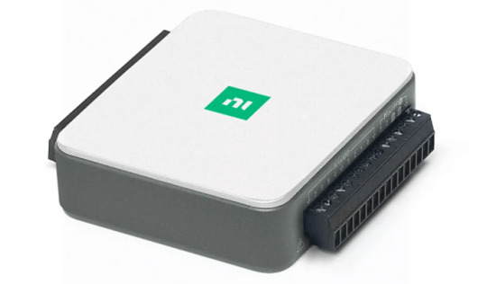
Description:
Multifunction I/O device
32-bit Counter
Data Logging
Portable Measurements
Data Acquisition system for Verification Validation
NI CDAQ 9185 for Data Acquisition
CompactDAQ Chassis – 4-Slot, TSN-Enabled Ethernet CompactDAQ Chassis
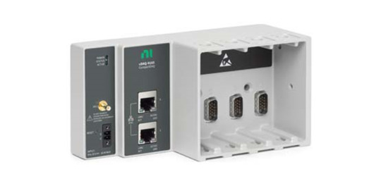
Description:
Controls Timing Synchronization between NI modules and host
Connectivity Options – USB, Ethernet, Wi-Fi
Multiple Hardware timed operations
For limited channel count data acquisitions which needs measurement from multiple networks, signals and sensors, the Compact DAQ is the ideal choice.
NI CDAQ 9181 for Data Acquisition
CompactDAQ Chassis 1 Slot, Ethernet CompactDAQ Chassis
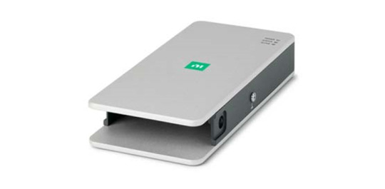
Description:
Created for compact, decentralized sensor measurement systems.
Manages the timing synchronization of NI modules with the host
May be used to produce a mix of analogue, digital, and counter/timer measurements by combining C Series I/O modules.
NI 9234 for Vibration Monitoring system
C Series Sound and Vibration Input Module, 2-Channel, 102.4 KS/s/Ch Simultaneous, ±5 V

Description:
Vibration and Sound Input Module
software-selectable coupling for AC/DC
IEPE short/open detection,
Signal conditioning for IEPE
Signal conditioning for IEPE
Comes with the NI DAQmx driver setup tool.
Supports Python, C++, and NI programming environments.
The system calculates displacement, velocity, and acceleration.
2 notes
·
View notes
Text
Basics and Applications of Optical Sensor

An optical sensor is one that converts light rays into a computerized signal. To measure a physical quantity of light and, depending on the sort of sensor, translate it into a form that is readable by some unified measuring device is the purpose of an optical sensor. Optical sensors can be both external and internal. External sensors assemble and address an appropriate quantity of light, while internal sensors measure the bends and other small changes in direction.
Types of Optical Sensors
There are various kinds of optical sensors, and here are the most common types.
Through-Beam Sensors The usual system consists of two independent components. The receiver and the transmitter are placed opposite to each other. That transmitter projects a light beam onto the receiver. A breach of the light beam is explained as a switch signal by the receiver. It is insignificant where the interruption appears.
Its advantage is that large operating distances can be attained and the recognition is separated from the object’s surface structure, colour or reflectivity.
It must be assured that the object is sufficiently huge to interrupt the light beam completely, to ensure a high operational dependability.
Diffuse Reflection Sensors Both receiver and transmitter are in one housing. The transmitted light is reflected by the object that must be identified.
The diffused light intensity at the receiver serves as the switching condition. Regardless of the sensitivity setting the front part regularly reflects worse than the rear part and this leads to the after effect of false switching operations.
Retro-Reflective Sensors Here, both transmitter and receiver are in the same house. Through a reflector, the radiated light beam is conducted back to the receiver. An interruption of the light beam commences a switching operation. It is not influential where the interruption occurs.
Retro-reflective sensors set up large operating distances with switching points, which are completely reproducible demanding little escalating effort. Any object interfering the light beam is precisely detected independently of its colour or surface structure.
#labview daq#LabVIEW consulting#labview projects#labview expert#labview developers#labview based projects#freelance labview projects
0 notes
Text
Ubidots + ESP32- Predictive Machine Monitoring
Predictive analysis of machine vibration and temp by creating mail events and a record of vibration in google sheet using Ubidots.

Story
Predictive Maintenance and Machine Health Monitoring
The rising of new technology i.e, the Internet of Things, heavy industry has started adopting sensor-based data collection to solve its biggest challenges, principal among them process downtime in the form of shutdowns and process delays. Machine monitoring also called predictive maintenance or condition monitoring is the practice of monitoring electrical equipment through sensors in order to accumulate diagnostic data. To achieve this, data acquisition systems and data loggers are used to monitor all kinds of equipment, such as boilers, motors, and engines. Following condition are measured:
Temperature and Humidity Data Monitoring
Current and Voltage Monitoring
Vibration Monitoring: In this article, we will read Temperature, vibration and publish the data in Ubidots. Ubidots supports graphs, UI, notifications, and emails. These features make it ideal for predictive maintenance analysis. We will also get the data in google sheets which will make predictive maintenance analysis more easier.
Hardware:
ESP-32
IoT Long Range Wireless Vibration And Temperature Sensor
Long-Range Wireless Mesh Modem with USB Interface
Software Used:
Arduino IDE
Ubidots
LabView Utility
Library Used:
PubSubClient Library
Wire.h
Arduino Client for MQTT
This library provides a client for doing simple publish/subscribe messaging with a server that supports MQTT
For more information about MQTT, visit mqtt.org.
Download
The latest version of the library can be downloaded from GitHub
Documentation
The library comes with a number of example sketches. See File > Examples > PubSubClient within the Arduino application.Full API Documentation.
Compatible Hardware
The library uses the Arduino Ethernet Client api for interacting with the underlying network hardware. This means it Just Works with a growing number of boards and shields, including:
Arduino Ethernet
Arduino Ethernet Shield
Arduino YUN – use the included YunClient in place of EthernetClient, and be sure to do a Bridge.begin() first
Arduino WiFi Shield - if you want to send packets greater than 90 bytes with this shield, enable the MQTT_MAX_TRANSFER_SIZE () option in PubSubClient.h.
Sparkfun WiFly Shield – when used with this library
Intel Galileo/Edison
ESP8266
ESP32The library cannot currently be used with hardware based on the ENC28J60 chip – such as the Nanode or the Nuelectronics Ethernet Shield. For those, there is an alternative library available.
Wire Library
The Wire library allows you to communicate with I2C devices, often also called "2 wire" or "TWI" (Two Wire Interface), can download from Wire.h
Basic Usage
Wire.begin()Begin using Wire in master mode, where you will initiate and control data transfers. This is the most common use when interfacing with most I2C peripheral chips.
Wire.begin(address)Begin using Wire in slave mode, where you will respond at "address" when other I2C masters chips initiate communication.
Transmitting
Wire.beginTransmission(address)Start a new transmission to a device at "address". Master mode is used.
Wire.write(data)Send data. In master mode, beginTransmission must be called first.
Wire.endTransmission()In master mode, this ends the transmission and causes all buffered data to be sent.
Receiving
Wire.requestFrom(address, count)Read "count" bytes from a device at "address". Master mode is used.
Wire.available()Returns the number of bytes available by calling receive.
Wire.read()Receive 1 byte.
Steps to send data to Labview vibration and temperature platform using IoT long-range wireless vibration, temperature sensor and long-range wireless mesh modem with USB interface:
First, we need a Labview utility application which is ncd.io Wireless Vibration and Temperature Sensor.exe file on which data can be viewed.
This Labview software will work with ncd.io wireless Vibration Temperature sensor only
To use this UI, you will need to install following drivers Install run time engine from here 64bit
32 bit
Install NI Visa Driver
Install LabVIEW Run-Time Engine and NI-Serial Runtime
Getting started guide for this product.
Uploading the code to ESP32 using Arduino IDE:
Download and include the PubSubClient Library and Wire.h Library.
You must assign your unique Ubidots TOKEN, MQTTCLIENTNAME, SSID (WiFi Name) and Password of the available network.
Compile and upload the Ncd__vibration_and_temperature.ino code.
To verify the connectivity of the device and the data sent, open the serial monitor. If no response is seen, try unplugging your ESP32 and then plugging it again. Make sure the baud rate of the Serial monitor is set to the same one specified in your code 115200.
Serial Monitor Output:

Data on serial monitor of Arduino IDE.
Making the Ubidot Work:
Create the account on Ubidot.
Go to my profile and note down the token key which is a unique key for every account and paste it to your ESP32 code before uploading.
Add a new device to your Ubidot dashboard name ESP32.


Now you should see the published data in your Ubidots account, inside the device called "ESP32".
Inside the device create a new variable name sensor in which your temperature reading will be shown.


Now you are able to view the Temperature and other sensors data which was previously viewed in the serial monitor. This happened because the value of different sensor readings is passed as a string and store in a variable and publish to a variable inside device esp32.
Create a dashboard in ubidots.

Go to data select dashboard and inside dashboard create different widgets and add a new widget to your dashboard screen.
OUTPUT
Now as the temperature/vibration increases and decreases new data available inside the various variable.

Creating Events in Ubidots

1) Select Events (from the Data dropdown).

2) To create a new event, click the yellow plus icon in the upper right corner of the screen.
Types of Events: Ubidots support already integrated events to allow you to send Events, Alerts, and Notifications to those who need to know when they need to know. Ubidots' prebuilt integrations include:
Email notifications
SMS notifications
Webhook events - learn more
Telegram notifications
Slack notifications - learn more
Voice Call notifications - learn more
Back to Normal notification - learn more
Geofence notifications - learn more
3) Then choose a device and associating variable that indicates the devices' "values".

4) Now select a threshold value for your event to trigger and compare it to device values and also select time to trigger your event.
5) Establish and configure which actions are to be executed and the message to the receiver: Send SMS, Email, Webhooks, Telegrams, Phone Calls, SLACK, and webhooks to those who need to know.

6) Configure the Event notice.

7) Determine the activity window the events may/may not be executed.

8) Confirm your Events.
The output of Event in Your Mail:

Export Your Ubidots Data to Google Sheets:
In this, we can extract the data stored in the Ubidots cloud for further analysis. The possibilities are enormous; for instance, you could create an automatic report generator and send them to your customers every week.
Another application would be device provisioning; if you have thousands of devices to deploy, and their information is in a Google Sheet, you could create a script to read the sheet and create a Ubidots data source for every line on the file. Steps to do this-
Create a Google Sheet and add two sheets to it with these names:
Variables
Values
From your Google Sheet, click on "Tools" then "Script Editor...", then "Blank Project".
Open the Script Editor.

Add the code below (in the code section) to the script Script.
Done! now open your Google Sheet again and you'll see a new menu to trigger the functions.

Result:

1 note
·
View note
Text
IoT Long Range Temperature And Humidity Sensor Using node-red

Things used in this project:
Hardware components
National Control Devices IoT Long Range Wireless Temperature Humidity Sensor
National Control Devices Long Range Wireless Mesh Modem with USB Interface
Software apps
LabView UtilityNode-Red
Node-Red
Story
Introducing NCD’s long-range wireless temperature-humidity sensor, boasting up to a 28 Mile range using a wireless mesh networking architecture. Incorporating the Honeywell HIH9130 temperature-humidity sensor transmits highly accurate temperature and humidity samples at user-defined intervals.
The onboard temperature sensor is rated for -25°C to 85°C or -13°F to 185°F and the humidity sensor is rated for 0 to 100% RH. It can be powered by just 2 AA batteries and an operational lifetime of 500, 000 wireless transmissions. Battery life can be extended up to 10 years depending on environmental conditions and the data transmission interval. Optionally, this sensor may be externally powered.
With an open communication protocol, this IoT wireless temperature humidity product can be integrated with just about any control system or gateway. Data can be transmitted to a PC, a Raspberry Pi, to Microsoft Azure® IoT, or Arduino. Sensor parameters and wireless transmission settings can be changed on the go using the open communication protocol providing maximum configurability depending on the intended application. The long range, price, accuracy, battery life and security features of Long Range Wireless Temperature Humidity Sensor makes it an affordable choice which exceeds the requirements for most of the industrial as well as consumer market applications.
Steps to Send Data to LabView Utility
At first, To visualize the data, we need a Labview utility application.
To use this UI, you will need to install the following drivers:
Install run time engine from here for 64-bit driver and 32-bit driver.
Install NI Visa Driver.
Install Labview Run time serial driver and LabVIEW Run-Time Engine.
Getting started guide for this product.
Setting Up Node-Red.
Now that you have sensors running, we need a way to do something useful with that data.
First of all, you’ll have to install Node-Red.
Once that’s done, you’ll need to enter your command line, or Power Shell for Windows users, navigate to the directory Node-RED is installed in.
Now type “npm I ncd-red-wireless node-red-dashboard“. This will install the nodes required to receive data from your wireless sensors and you can start Node-RED once this is done.
To start node server write node-red in the command prompt or terminal and press enter.
Steps to Build the Flow:
Step 1: At this point, you’ll be viewing a large blank flow with a long list of nodes on the left-hand side, this sidebar is called the palette.

Step 2: Go ahead and drag a Wireless Gateway node over to your flow canvas to get started.

NCD-red-wireless Provides the nodes that manage the serial connection, parse incoming sensor data, filter it by specific parameters, and allow you to configure the wireless sensors.
Step 3: Finding Your Wireless Sensors:
When you’ve delivered the node you’ll be able to view the info tab, which contains records about the node’s capability, this tab is well populated for maximum node-red packages and consists of treasured statistics, often you will now not want to view any other documentation outdoor of the info tab, so hold it in thoughts even as you’re building your flows when you have a question approximately how a node works. The next element we want to do is configure the node, when you first add it you’ll note that there is a small triangle at the top right corner next to a blue dot, the triangle indicates that the node wishes extra configuration, the blue dot indicates that the node has no longer but been deployed as part of the flow.
Double click on the node to open up the configuration options.
Click on the pencil icon next to the Serial Device field to configure your USB router, this will open a second configuration panel that only has a few options.

Step 4: Click on the magnifying glass next to the Serial Port field and select the port that corresponds with your router, then click the “Add” button on top.

Step 5: The Serial Device field will now be populated based on that selection, and you can click “Done”, you now have direct access to your wireless sensors! To view the data coming in.

Step 6: Now Go Back to Your Palette and Type “debug” Into the Search Field at the Top, Grab One of These Nodes and Drag It to the Right of Your Wireless Gateway.

Step 7: Double Click on It and Change “msg.” to “complete Msg Object” Click Done.

Step 8: Now draw a line between the two nodes, and click “Deploy” on the top right of the window.

Step 9: Working with the data
Now out of your wireless sensors data is gathered and it is output to the “debug” tab, this “debug tab” is placed within the right sidebar subsequent to the information tab. To see the information is available to hit the reset button. In node-red records is surpassed among nodes in a JSON packet. When the msg object comes into the debug tab you may make bigger it to view the overall list of information that comes with it. This is extraordinarily useful in case you need to quickly see which sensors are checking in. The other issue this node gives is an easy way to interchange your router to the network identity that devices in configuration mode document on, simply hit the button on the left of the node and the tool will switch to the configuration network, hit it once more to return it to listening mode. Once we get the wi-fi tool nodes set up, they may be set to routinely configure a sensor whilst it enters configuration mode, so it’s always available to maintain such gateway nodes present at the flow for speedy configuring a device.

Step 10: Adding the wireless sensors
we need to separate wireless sensor records domestically in order that we are able to display it, we could use a switch node to split out the messages from the gateway based totally on the mac address with or sensor type, but as I referred to, the wireless nodes truly incorporate extra functionality for configuring the sensors, so we’ll start with them to give you an extra entire image of how those structures can work. In case you haven’t already seen packets coming in from both of your sensors, cross in advance and hit the reset button on the only that hasn’t started. While a sensor assessment in through any serial device configuration node, the mac address and kind of sensor is cached in a pool so we are able to quickly find it for the duration of this next step.
Grab a Wireless Node from the palette and drag it onto the flow, double click on it to get it configured.

Step 11: select the serial device from the drop-down that you used for the Wireless Gateway.

now click the magnifying glass next to “Mac Address” and select one of the available options.

You’ll notice this automatically sets the sensor type for you, you can also give it a name to make it easier to identify. As noted in the info tab, the Serial Device for Config field is optional, and we won’t worry about it right now. The node you have just added effectively works as a filter on incoming sensor data, only passing through data for the mac address, or sensor type if no mac address is present.
Step 12: Displaying Up the Temperature/Humidity:
These nodes for the wireless sensors output a msg object with all of the same information as the Wireless Gateway node, just in a slightly different format, the Sensor Data itself is sent in the msg.payload, which is what most nodes use to interact with the msg itself.
Grab a “split” node from the palette, and place it to the right of the Temp/Hum node.

Step 13: double click and check the box under Object that says “Copy key to”, this will split the msg into multiple objects, one for each property in the payload, and set the topics for those new msgs to the property names.

Step 14: Now Add a “switch” Node, This Will Allow Us to Send Each Msg to a Specific Part of the Flow, One to Handle Temperature, and One Humidity. in the First Field Change “payload” to “topic”, Next to the “==”, Type “temperature”.

Step 15: Then click the “+add” button at the bottom left, in the new field type “humidity”. As you can see each of these has a unique number to the right, this number indicates which output the msg will be sent to when it matches the condition.

Step 16: Next let’s add a “gauge” from the palette.

Step 17: set the Label to “Temperature”, and the Value format to “{{value | number:2}}”, and the Units to “Celsius” you can alter the range to the minimum and maximum expected temperature, I’m using 0 and 50.

Another really cool feature of the flow builder is copy+paste, click on the gauge you just added and click ctrl+c (cmd+c on mac), then cntl+v, now you have a second gauge, double click on it to change the Label to Humidity, the Units to RH, and the range to 20 and 80.

Step 18: Now draw wires from the Temperature/Humidity node to the split node, from the split node to the switch node, and from the switch node’s first (top) output to the temperature gauge node, and from the switch node’s second output to the humidity gauge.

Once that’s done click deploy.
Step 19: NODE-RED DASHBOARD:
Provides the ability to create a UI using the flow builder, provides charts, graphs, and a number of other visual elements we can use to display data, along with nodes to trigger a flow using user input. We will use some of these nodes to display the telemetry from your wireless sensors.
let’s check it out! There is a tab on the top right that says “Dashboard”.

Step 20: on the top right of that tab is the little “new window” icon, click on it to view your UI.

It is likely that the gauges aren’t displaying any information, because no sensor data has been reported since you deployed the flow, click the reset button on your temperature/humidity sensor to force it to check in and your gauges should jump up. You should now have real-time data displaying!
Step 21: NODE-RED DASHBOARD OUTPUT:
Now as the temperature and humidity increases and decreases new data available inside the various variable.

Node_red_flow
Below is an export of the complete dashboard setup I built for these wireless sensors.
https://github.com/ncdcommunity/Ncd-Long-Range-Temperature-and-Humidity-Sensor-with-Node-Red/blob/master/node%20red%20flow.json
1 note
·
View note
Text
Writing ssh shell from labview on compactrio

WRITING SSH SHELL FROM LABVIEW ON COMPACTRIO HOW TO
WRITING SSH SHELL FROM LABVIEW ON COMPACTRIO FULL
WRITING SSH SHELL FROM LABVIEW ON COMPACTRIO SOFTWARE
Step 1: Enabling Secure Shell Server (sshd) If using the myRIO, the easiest way to do this is to configure the Wi-Fi interface to that it connects to your internet hotspot and acquires address, dns, gateway via dhcp. Without internet access, this will not work. NOTE: All steps assume the cRIO has internet access. This tutorial will guide you through the process. This may sound hard, but it really isn't. This includes setting up the build environment on the cRIO, cloning the git repository for the rtl-sdr library, and finally compiling the code. This tutorial therefore focuses on this portion:īefore beginning with actual Labview programming, we need to prepare the cRIO. The next tutorial will implement and FPGA FFT to accelerate things, and in chapter 4 we will put this whole thing together into a coherent, expandable system. In this tutorial, we will be focusing on getting the rtl-sdr library working on in the cRIO.
WRITING SSH SHELL FROM LABVIEW ON COMPACTRIO FULL
This leads the reader chapter by chapter to a full solution, and hopefully makes things more understandable. In order to keep the reader interested and to keep the chapters short and manageable, I have decided to split things up a bit. Simply put, we want to turn the myRIO into an SDR-instrument that we can send commands to and have it return processed data to the host. However, it also makes things more complicated because a command framework is required from the Host PC to the cRIO RT target. This has the advantage of getting rid of the latency of the USB LAN connection during acquisition. In order to shorten this path it is possible to perform the acquisition directly on the cRio RT target. The FFT and other DSP is done in the FPGA and the resulting information flows back up to the PC. The information flows from the RTL-SDR to the Host PC via USB, then to the RT system via USB LAN (in the myRIO case), then to the cRio FPGA via a DMA FIFO. If the host is used for acquisition, the information flow is pictured above. If we want to use the cRIO (especially the FPGA) to accelerate digital signal processing, it is necessary to stream the information to the RT system, and then to the FPGA. The myRIO used here has the following parameters: NOTE: All development was done using Labview 2016, 32-bit. Unfortunately, there is probably no reasonable way to compile this library on VxWorks, much less Pharlap, so users of older CompactRIO devices are on their own. I used a myRio to do this project, but it should be possible to use this information on any linux-based cRio.
WRITING SSH SHELL FROM LABVIEW ON COMPACTRIO HOW TO
In this post I will go a step further and show the reader how to compile the rtlsdr library directly on an RTLinux cRIO. Additionally, because the library is open source, header files and with that the library’s entry points are available to us in a usable and documented format. The implementation process was very straightforward because the library was already compiled and available in binary form.
WRITING SSH SHELL FROM LABVIEW ON COMPACTRIO SOFTWARE
In my previous post ( ), I released a library which allows a Labview user on Windows to directly use RTL-based software defined radios.
0 notes
Text
How to install labview on linux

#How to install labview on linux how to#
#How to install labview on linux install#
#How to install labview on linux full#
If an existing instance is running, the existing instance opens the VIs passed in the command line, and the new instance of LabVIEW quits silently. If you would like further information, need help or assistance please contact us we have many years of experience and have expert knowledge and expertise to assist you with your project. quoteHelp for the -launch command-line argument on UNIX/Linux plaformsLabVIEW launches and checks for an existing instance of LabVIEW already running on the same display. This is of even greater relative importance when you take into account the client running a Linux environment is likely a high level academic center, a military-grade national security client, or some other similar immensely complicated data center. Imagine the time savings when your programming and engineering teams will be able to collaborate together in real time, without language barriers, due to the virtues of graphical programming. Use the built in sensor VIs to start get.
#How to install labview on linux install#
You will find that your memory and processing requirements will go way down when you have a proper programming environment in place, and that the benefit of having everything standardized is of immense value to large organizations. LINX provides easy to use VIs for interacting with common embedded platforms like Arduino, chipKIT, Teensy and more. Installing LabVIEW in Linux Mint 20.3 Trying to install this piece of proprietary software because my school wants me to is quite painful, but here is what I did Published, 614 words, 2 min. So take a look at LabVIEW and begin imagining how you can take advantage of the programming power of graphical execution to improve your own data systems. Install LabVIEW Modules and Toolkits NI-VISA Available through the LabVIEW INSTALL script NI-DAQmx /info. Ultimately, anything that you can build on any singular version of any OS should be able to be compiled and run on your Linux system with the same functionality. If you use LabVIEW and have development applications you built using the Windows environment, you are even able to get run-time support directly from NI. Upon software installation, all of the API Vis are directly loaded documentation is fully available.
#How to install labview on linux full#
Other Important FactorsĪnother important function is the fact that it comes with full API support for each driver. You will also be able to run fully functional LabVIEW Graphical User Interfaces (GUIs) off of the Raspberry Pi. The downloaded code will execute embedded and standalone on the Raspberry Pi.
#How to install labview on linux how to#
Multiple operating systems as long as they are able to support all of The LabVIEW for Raspberry Pi is a compiler that takes a LabVIEW program, compile and download it to Raspberry Pi single board computers. In this video I cover how to install Linux-TKG, a custom Linux kernel designed for gaming on Ubuntu, Fedora and OpenSUSE based distributions. These tools will allow users to develop executables that will runĭirectly from LabVIEW to Linux applications, which are portable to Control, Design, and Simulation Modules for Linux Environments.The Application Builder Environment for Linux Development.
0 notes
Text
Labview for mac 10.68

#LABVIEW FOR MAC 10.68 FOR FREE#
#LABVIEW FOR MAC 10.68 FOR MAC OSX#
#LABVIEW FOR MAC 10.68 MAC OS X#
#LABVIEW FOR MAC 10.68 INSTALL#
#LABVIEW FOR MAC 10.68 FULL#
I've also added a link on the Spectroscopy page. NI LabVIEW Run-Time Engine 8.6 Free Software Download.
#LABVIEW FOR MAC 10.68 MAC OS X#
Select Mac OS X 10.6 from the Base SDK sub-section. Operating system compatibility can also be. Using incompatible versions is not supported and may result in errors.
#LABVIEW FOR MAC 10.68 INSTALL#
Reference this information to ensure you install the correct version when upgrading or updating your operating system, or when migrating or porting code to a new system. In the section called Architectures, click the Architectures sub-section and select Other. The following table shows the compatibility between LabVIEW versions and different macOS operating systems. Using these development softwares, researchers have prototyped many of the most used radio standards. Right-click on your project’s blue icon and select Get Info. Using the LabVIEW Run-Time Engine - LabVIEW 2017 Help. suite, simulink and labView SDR packages. This version will support all executables built with.
#LABVIEW FOR MAC 10.68 FULL#
LabVIEW 8.5 Run-Time Engine (Standard) gives full support for executables.
#LABVIEW FOR MAC 10.68 FOR FREE#
A wrapper shell script called "coot" will reside in /usr/local/bin/coot when you are done.Ĭoot (Crystallographic Object-Oriented Toolkit) is for macromolecular model building, model completion and validation, particularly suitable for protein modelling using X-ray data.Ĭoot displays maps and models and allows model manipulations such as idealization, real space refinement, manual rotation/translation, rigid-body fitting, ligand search, solvation, mutations, rotamers, Ramachandran plots, skeletonization, non-crystallographic symmetry and more. Download labview run-time engine 2013 for free (Windows) Download NI LabVIEW Run-Time Engine. The package installer will install everything in /Library/Coot. The 10.6 version should run on 10.6.8 or greater. I have two versions, built on two different computers. For more information, please read the End-of-Life Announcement for DAQmx Base Driver. Double click the file name LabVIEW2020Eval.dmg and then click on Download. Note: NI-DAQmx Base is compatible with macOS 10.14 and earlier versions check NI-DAQmx Base and macOS compatibility for all supported versions for this driver. Click on Mac Software on the top menu bar. With considerable help from Nat Echols, we can now build coot automatically every night a new revision is available. LabVIEW MathScript RT Module for Mac/Linux.
#LABVIEW FOR MAC 10.68 FOR MAC OSX#
Light emitting diodes (LEDs) showed their effective importance in the promising pest management tools which could be used easily with certain effects on the exposed pest.A reader sent me a link to a posting on the brilliant Crystallography on OS X website highlighting the availability of a stand alone version of Coot for Mac OSX It could be concluded that, a close relation between biogenic amines affected by LEDs which contributed as an antifeedant till mortality. Monoamine oxidase (MAO) was determined in S.littoralis homogenates and LEDs showed its effect as an effective inhibitor of the enzyme activity significantly. Besides, malformation was noticed in all stages with different percentages decreased gradually from 1st to 4th larval instars. To turn your acquired data into real business results, you can develop algorithms for data analysis and advanced control with included math and signal processing IP or reuse your own libraries from a. Mean weights of exposed larvae to White and Blue LEDs were lower than control with significant difference at the end of each stage. LabVIEW enables you to immediately visualize results with built-in, drag-and-drop engineering user interface creation and integrated data viewers. LEDs have an antifeedant effect against S. motion analysis was accomplished through the use of a Mac Reflex visual. Using LabVIEW, scientists and engineers can acquire data from a variety of sources. While, Blue LED caused mortality with 96.67, 90, 86.67 and 80 % against the same mentioned larval stages resp. in conjunction with a LabVIEW VI to simultaneously control motor movement and. LabVIEW, from National Instruments, is a graphical programming environment designed specifically for scientists and engineers who need to acquire, analyze, and present scientific data or to control automated processes. White LEDs were more effective against all larval stages more than Blue LEDs even mortality ratios proved that.White LEDs caused 100 % mortality of both 1st and 2nd stages, and recorded 96.67% and 90% of 3rd and 4th larval stages. Laboratory studies were conducted to determine the mortality and both of antifeedant and growth inhibitory effects of light-emitting diodes (LEDs) against 1st, 2nd, 3rd and 4th larval stages of S.littoralis. Light Emitting Diodes (LEDs), which showed a direct effect on pests, were powered by solar energy to play an indirect role in controlling Spodoptera littoralis.
0 notes
Link
Skive Projects - Project center in chennai.
#final year project center in chennai#best final year project center in chennai#best project center in chennai#project center in chennai#ieee project center in chennai#mechanical project center in chennai#biotechnology project centers in chennai#engineering project centres in chennai#ece project center in chennai#matlab project center in chennai
0 notes
Text
Monitoring System for ECG
Bruce Stanko says that , An ECG monitoring system monitors and records a patient's heart rate. The monitor's data is saved in a computer. This ECG monitor allows a doctor to monitor a patient without being in the same room. The project's goal is to overcome typical ECG data collection issues. It also intends to enable remote ECG signal transfer from patient to doctor. A portable wireless ECG monitoring system may perform the same duties as a centrally located ECG equipment while connecting to other wireless devices. Electrode micromodules are digitally processed and sent. It used ZigBee module transfer. The monitoring system can then be moved to another location. The project was finished and is now being pushed as a realistic alternative in healthcare. Bruce Stanko Described ,Basically, it's a portable ECG terminal and a health monitoring center. The health monitoring center communicates with the portable ECG through Zigbee. The ECG signals are used to monitor the patient's status and treat them. This project employs a low-power PIC16F877 microcontroller. The pin configuration is illustrated below. A ATmega328P microprocessor powers the DPU. It can show the P wave, QRS complex, and T wave of an ECG signal. This project's findings are comparable to the MATLAB GUI design. The labVIEW GUI design is compatible with MATLAB and LabVIEW. The device also has a software interface for diagnosing cardiac activit During the design phase, a one-cycle ECG will be shown. ECG signal with T, P and QRS waves. In the atria, the T wave tells us how long it takes for the electric impulse to reach the ventricles. The QRS complex wave has a high R and a small S. A P wave and a T wave follow the T wave. It will be utilized as a detection and measurement processor during design. The MSP430 will handle the electrocardiogram and heart rate. Based on a low-pass filter, the project will remove high-frequency noise. The MSP430 will process the QRS wave and heart rate. The data will be sent to a computer or a ZigBee network. Bruce Stanko suggest that ,After processing the ECG signal, the gadget applies initial amplification. Its CMRR must be 120 dB to prevent signal deterioration. An ECG's gain should be 13 mV. Essai d'utilisation A good ECG signal may be read in a few ticks. The equipment should additionally capture the patient's pulse in addition to their heart rate. After collection, the ECG signal is notch filtered to decrease 50 Hz power line interference. The result is a clean ECG. The DAU is built on this method. It's in medical devices. This is a low-cost heart rate monitor. This will improve monitoring. In reality, a $20 ECG monitor can be made. The ECG signal is subsequently low-pass filtered after the active high-pass filter. Filtering out high-frequency noise with low pass filters. The ECG signal is more accurate after a low-pass filter. It will also eliminate electrode frequency offsets and minimize low-frequency noise. It has an active high-pass (low-pass) filter.
0 notes
Video
youtube
Industrial Pollution Monitoring using LABVIEW and Arduino | Industrial Air Pollution Monitoring System using LabVIEW and Zigbee | Smart Environmental Monitoring System Using Labview | Air Pollution Monitoring System using LabVIEW | iot based air pollution monitoring system | iot based air pollution monitoring system ppt | Smart Sensor Network Based High Quality Air Pollution | Industrial pollution monitoring system using LabVIEW and GSM | Smart Environmental Monitoring System Using Labview.***********************************************************If You Want To Purchase the Full Working Project KITMail Us: [email protected] Name Along With You-Tube Video LinkWe are Located at Telangana, Hyderabad, Boduppal. Project Changes also Made according to Student Requirementshttp://svsembedded.com/ https://www.svskits.in/ http://svsembedded.in/ http://www.svskit.com/M1: 91 9491535690 M2: 91 7842358459 We Will Send Working Model Project KIT through DTDC / DHL / Blue Dart / First Flight Courier ServiceWe Will Provide Project Soft Data through Google Drive1. Project Abstract / Synopsis 2. Project Related Datasheets of Each Component3. Project Sample Report / Documentation4. Project Kit Circuit / Schematic Diagram 5. Project Kit Working Software Code6. Project Related Software Compilers7. Project Related Sample PPT’s8. Project Kit Photos9. Project Kit Working Video linksLatest Projects with Year Wise YouTube video Links157 Projects https://svsembedded.com/ieee_2022.php135 Projects https://svsembedded.com/ieee_2021.php 151 Projects https://svsembedded.com/ieee_2020.php103 Projects https://svsembedded.com/ieee_2019.php61 Projects https://svsembedded.com/ieee_2018.php171 Projects https://svsembedded.com/ieee_2017.php170 Projects https://svsembedded.com/ieee_2016.php67 Projects https://svsembedded.com/ieee_2015.php55 Projects https://svsembedded.com/ieee_2014.php43 Projects https://svsembedded.com/ieee_2013.php1100 Projects https://www.svskit.com/2022/02/900-pr...***********************************************************2. Air pollution monitoring system using LabVIEW - IEEE Xplore Document,3. Industrial pollution monitoring system using LabVIEW,4. WSN Based Real Time Air Pollution Monitoring System Using Zigbee,5. Industrial Pollution Monitoring System Using LabVIEW | International,6. NI Pollution Monitoring
0 notes